H7Plus Autopilot Flight Controller Manual
LAYOUT
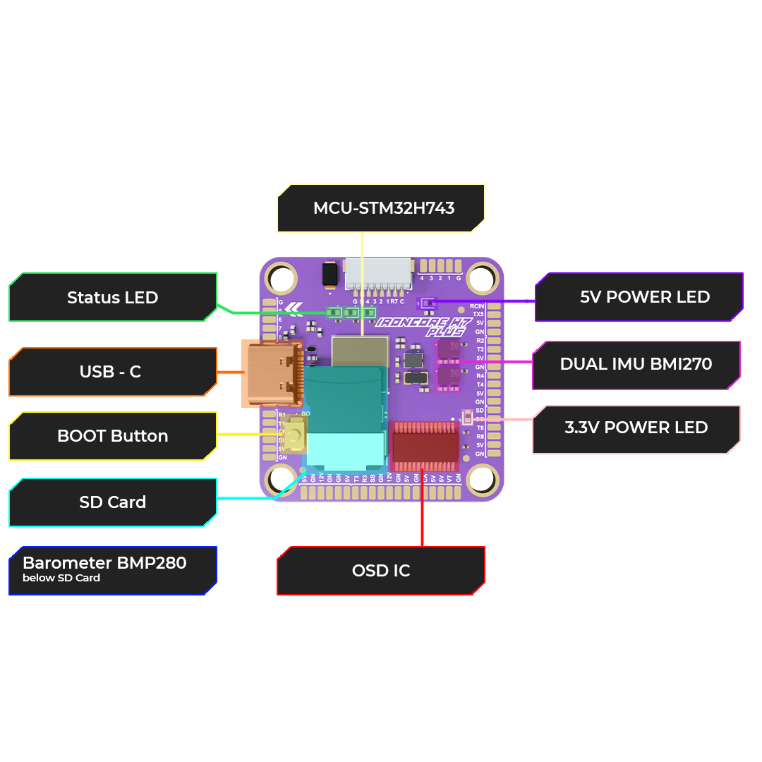
Front Layout
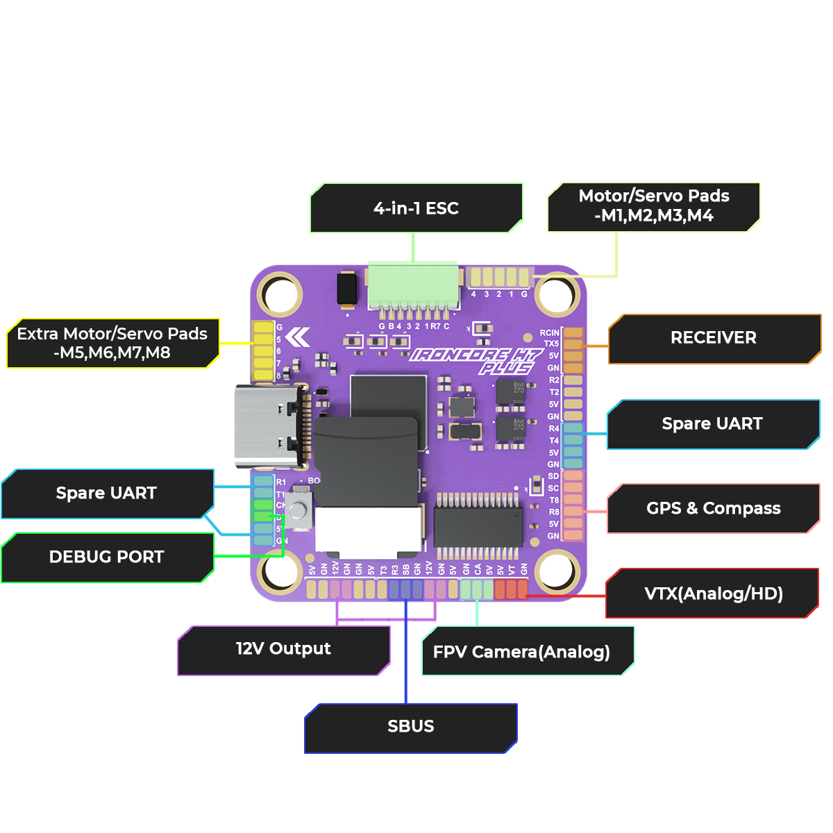
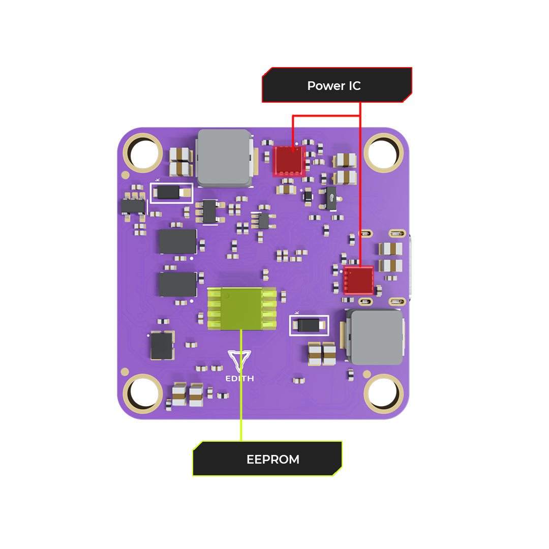
Back Layout
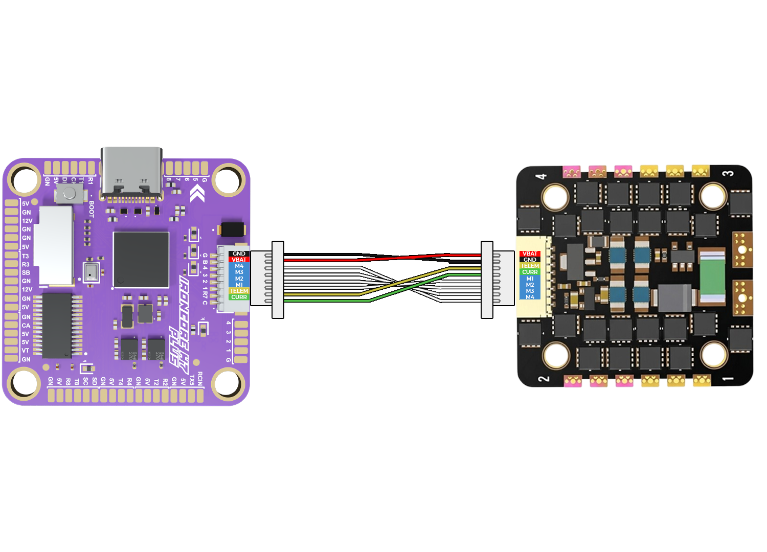
FLIGHT CONTROLLER TO ESC CONNECTIONS USING CONNECTOR
Connect the flight controller to the ESC using the provided multi-wire connector. This link carries throttle signals, telemetry, and power (if supported), ensuring clean and reliable communication between the FC and ESC. Note: Ensure correct connector orientation and secure fit before powering the system.
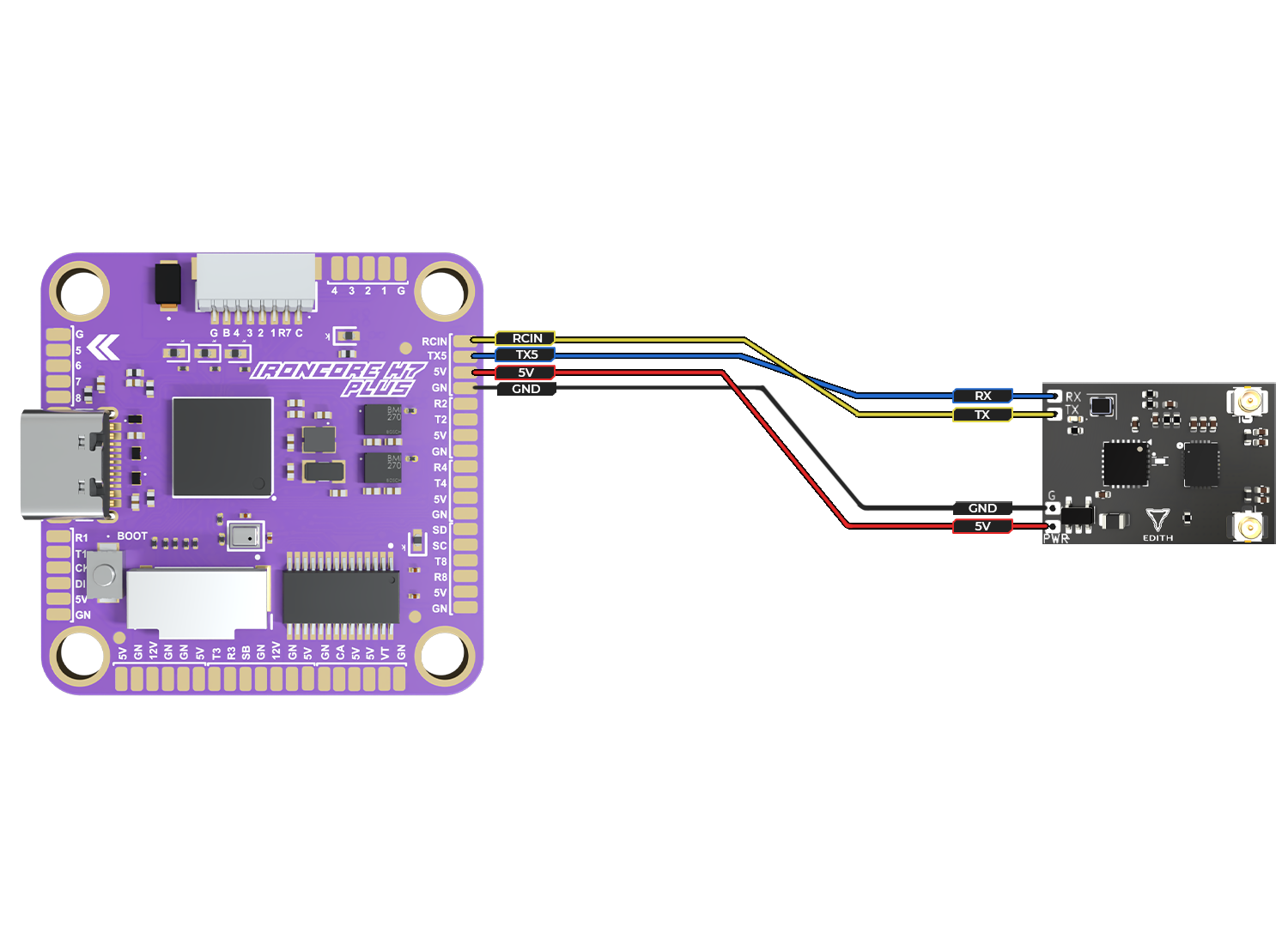
FLIGHT CONTROLLER TO ELRS CONNECTIONS CONNECTOR
Connect the ELRS receiver to the flight controller using UART interface: 5V and GND for power, TX (receiver) to RX (FC), and RX (receiver) to TX (FC). This enables reliable control signal communication. Note: Always cross TX ↔ RX lines and verify the correct UART port in firmware configuration.
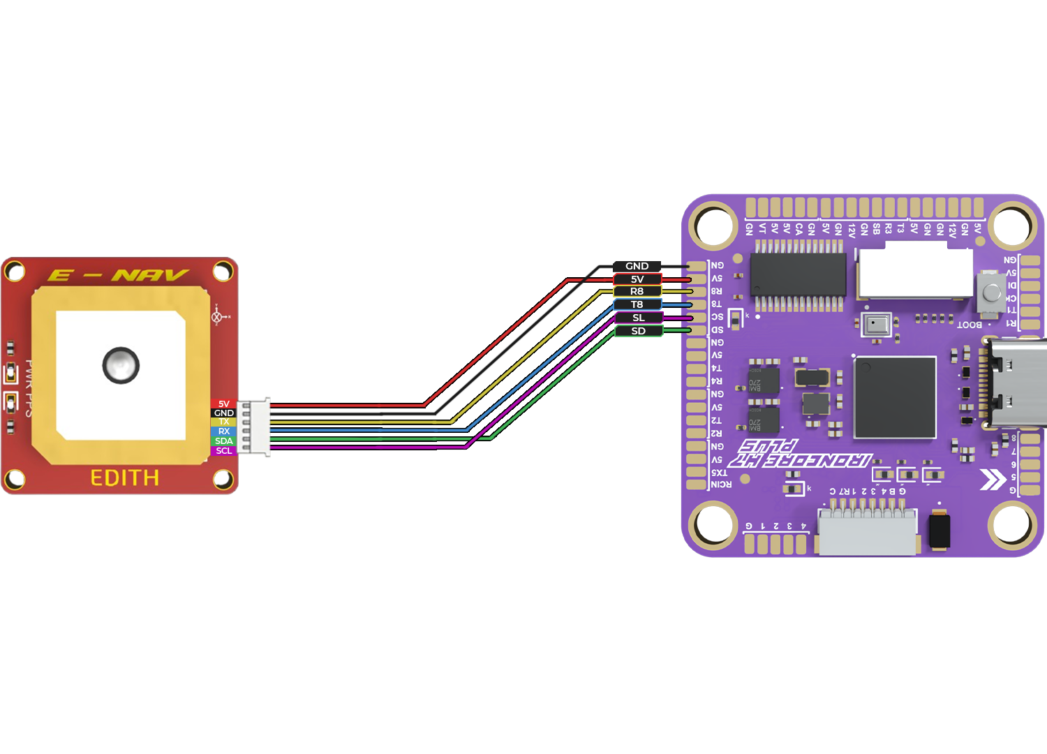
FLIGHT CONTROLLER GPS CONNECTIONS
Connect the GPS module to the flight controller using UART: 5V and GND for power, TX (GPS) to RX (FC), and RX (GPS) to TX (FC). Additional SDA/SCL lines are used for compass (I2C) communication if available. Note: Mount the GPS module away from power electronics and ensure correct UART and I2C configuration in firmware.
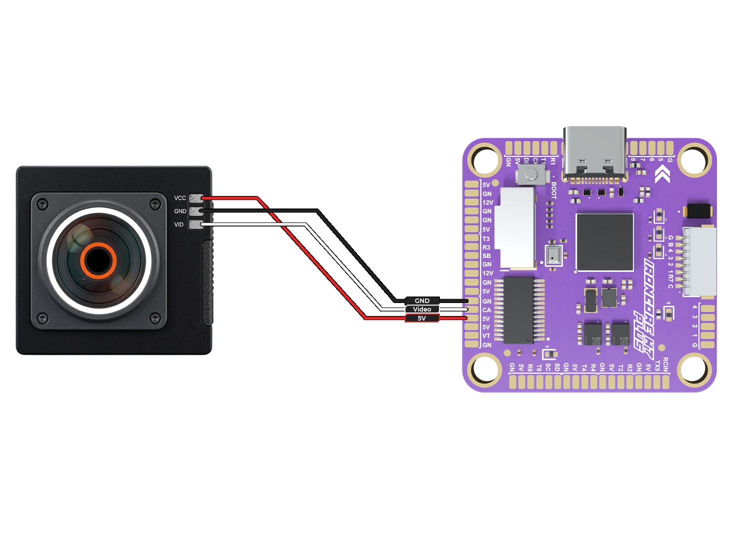
CAMERA CONNECTION
To enable the FPV feed and On-Screen Display (OSD), connect the camera using:
VCC (Red): Connect to 5V pad on FC
GND (Black): Connect to GND pad
VID (White/Yellow): Connect to CAM (Video In) pad
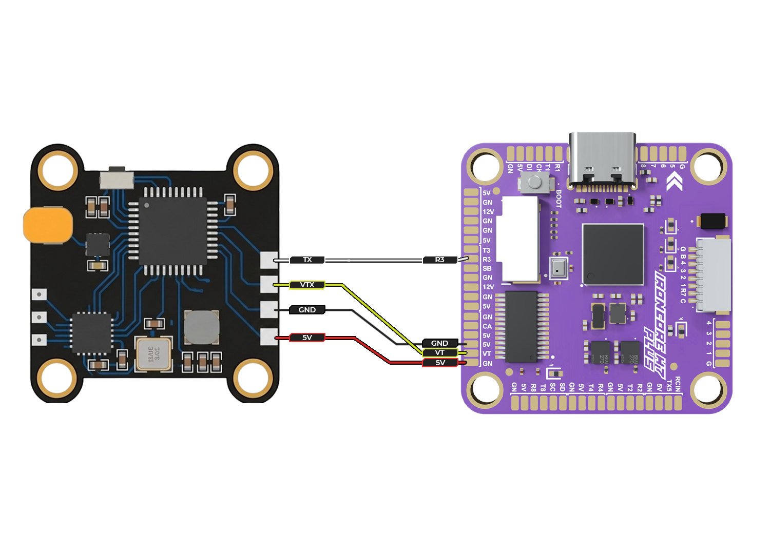
FLIGHT CONTROLLER VTX CONNECTIONS
This connection transmits the processed video signal (with OSD) from the flight controller to your Video Transmitter (VTX) for wireless broadcast.:
VCC (Red): Powers the VTX from the flight controller’s 5V pad.
GND (Black): Connects to the GND pad to complete the power circuit.
VT (Yellow): Connects the VTX video input to the VT (Video Out) pad on the flight controller.
TX (White): Connects to the R1 (UART1 Receive) pad. This enables SmartAudio or Tramp protocols, allowing you to change VTX channels and power levels via your radio sticks.
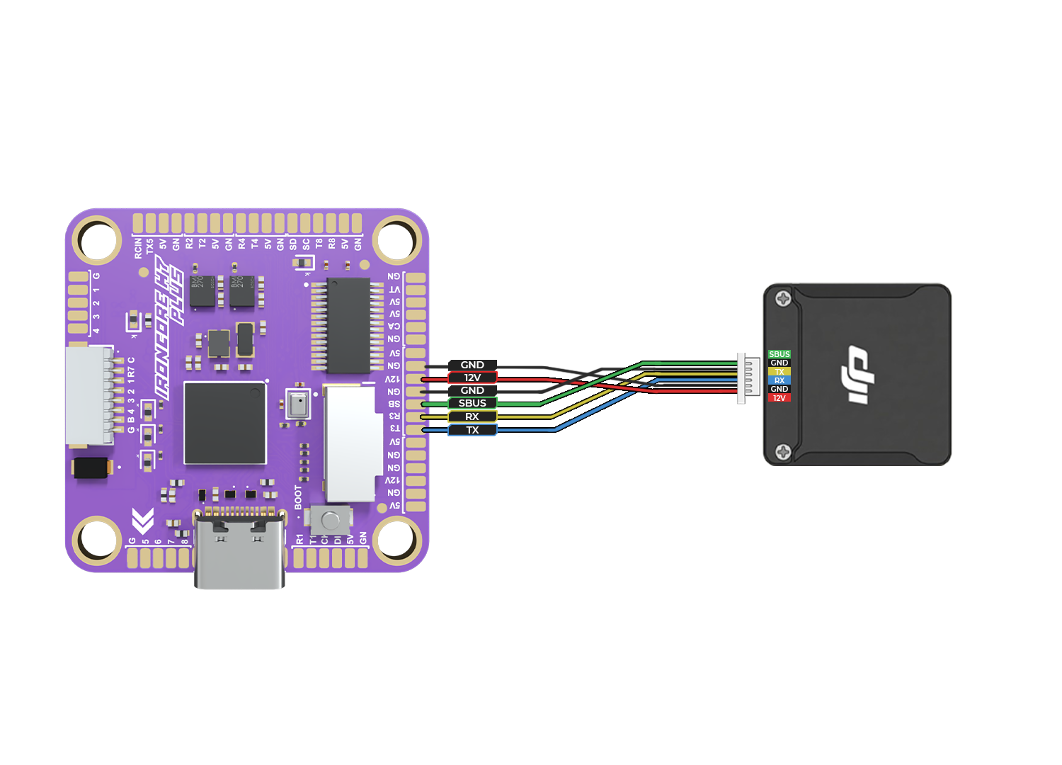
FLIGHT CONTROLLER DJI 03 CONNECTIONS
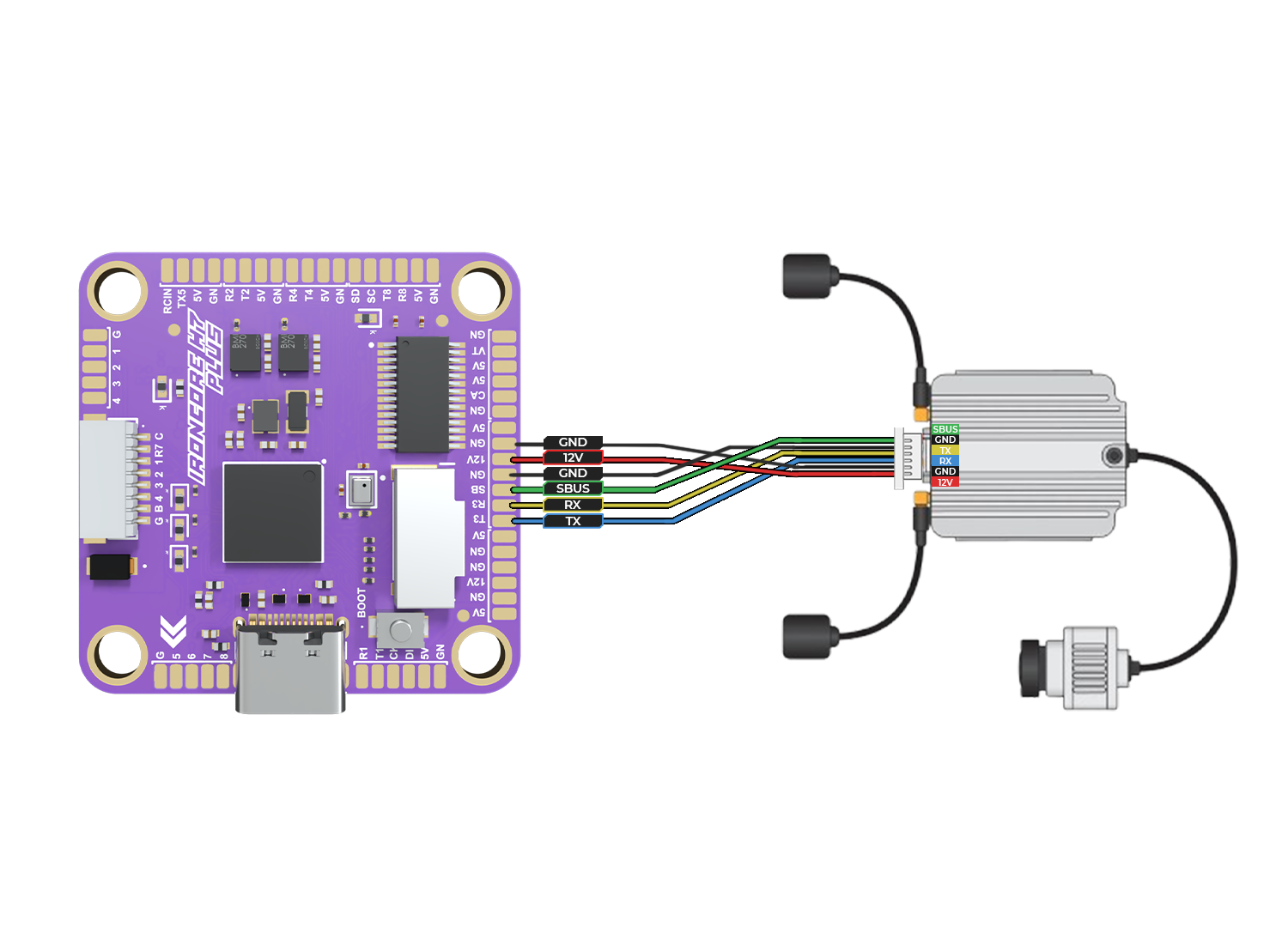
Connect the DJI O3 Air Unit to the flight controller via UART: power (5V/VBAT as required), GND, TX (FC) to RX (O3), and RX (FC) to TX (O3). The SBUS wire from the O3 can be connected to the FC’s SBUS/RC input for direct receiver signal output.
Note: Enable MSP/OSD on the selected UART and configure SBUS input in firmware if using the O3’s built-in receiver output.
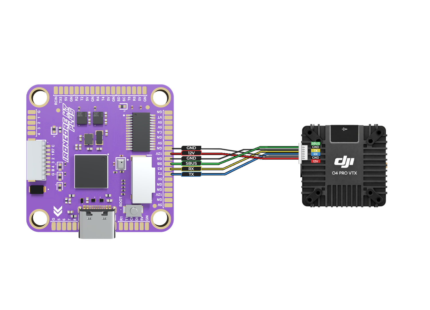
FLIGHT CONTROLLER DJI O4 PRO CONNECTIONS
Connect the DJI O4 Pro Air Unit to the flight controller via UART: power (5V/VBAT as required), GND, TX (FC) to RX (O4), and RX (FC) to TX (O4). The SBUS wire from the O4 Pro can be connected to the FC’s SBUS/RC input for direct receiver signal output.
Note: Enable MSP/OSD on the selected UART and configure SBUS input in firmware if using the O3’s built-in receiver output.
Note: Enable MSP/OSD on the selected UART and configure SBUS input in firmware if using the O4 Pro built-in receiver output.
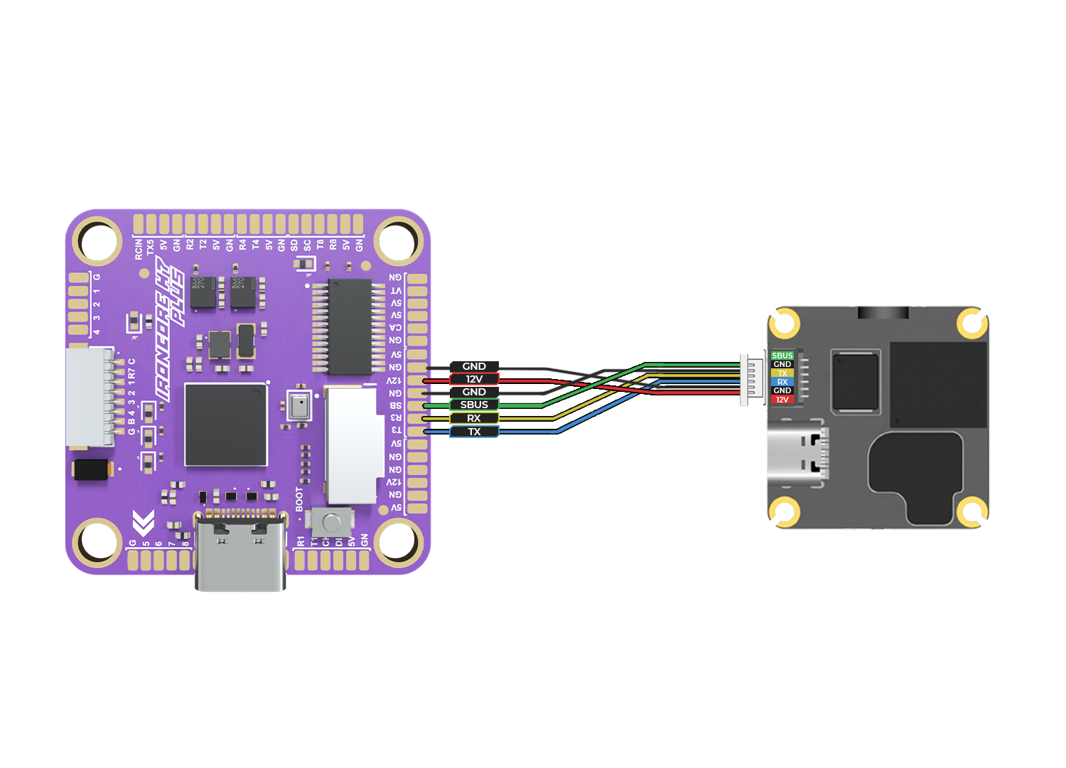
FLIGHT CONTROLLER DJI O4 lITE CONNECTIONS
Connect the DJI O4 Lite Air Unit to the flight controller via UART: power (5V/VBAT as required), GND, TX (FC) to RX (O4), and RX (FC) to TX (O4). The SBUS wire from the O4 Lite can be connected to the FC’s SBUS/RC input for direct receiver signal output.
Note: Enable MSP/OSD on the selected UART and configure SBUS input in firmware if using the O4 Lite built-in receiver output.
FLIGHT CONTROLLER DJI AIR UNIT CONNECTIONS
Connect the DJI Air Unit to the flight controller via UART: ppower (5V/VBAT as required), GND, TX (FC) to RX (Air Unit), and RX (FC) to TX (Air Unit). The SBUS wire from the Air Unit can be connected to the FC’s SBUS/RC input for direct receiver signal output.
Note: Enable MSP/OSD on the selected UART and configure SBUS input in firmware if using the Air Unit built-in receiver output.